A commercial aircraft brings together thousands of structural components and multiple systems that must operate as an integrated whole. The fuselage, wings, landing gear, engines, electrical systems, hydraulic systems, pneumatic systems, and emergency equipment form an architecture designed to withstand loads, support safe flight, and provide redundancy for essential functions.
This material provides a concise educational overview for study purposes. System architecture, component quantities, equipment locations, and specific operating principles vary by manufacturer, aircraft model, and generation. Approved aircraft and manufacturer documentation must always be used for actual maintenance and operational procedures.
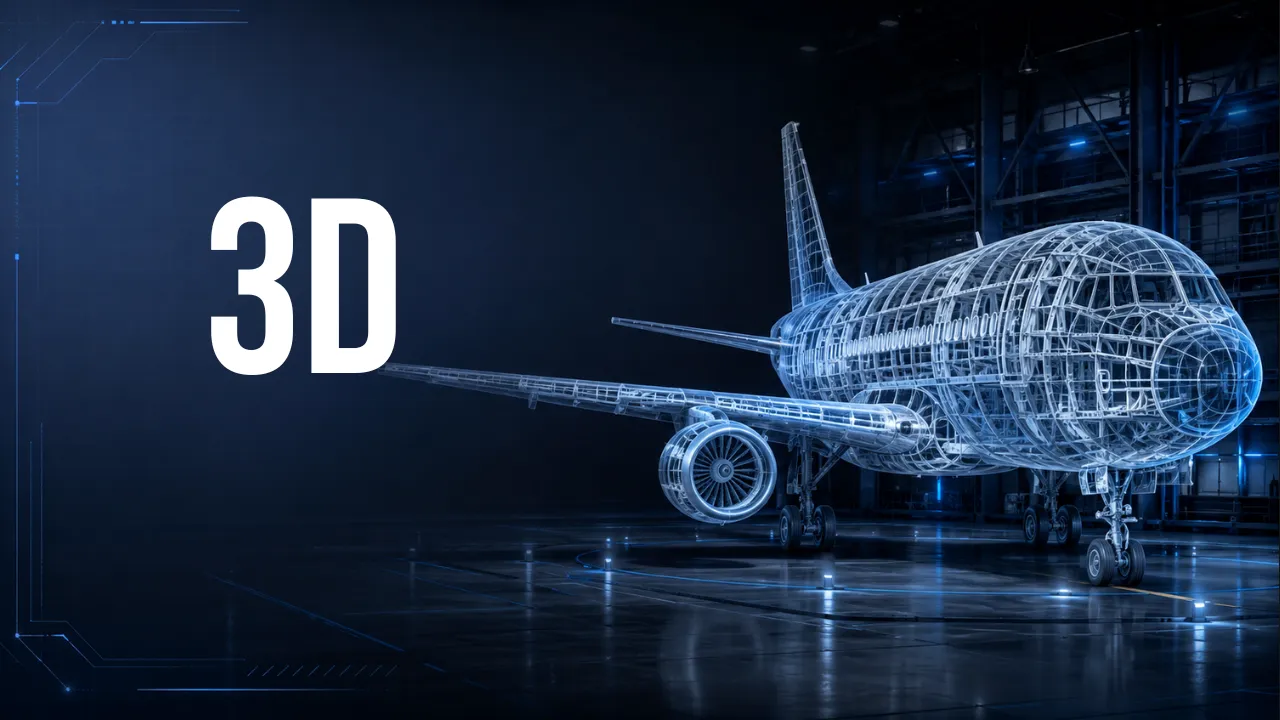
See where many of these structures and systems are located inside a commercial aircraft through a detailed 3D visualization.
▶ WATCH THE FULL 3D AIRCRAFT VIDEO1. General Aircraft Structure
The fuselage must be both strong and relatively lightweight. In conventional semi-monocoque structures, the structural skin works together with frames, stringers, longerons, beams, bulkheads, and reinforcements to distribute loads generated during flight and ground operations.
Aluminum and aluminum alloys remain widely used in aircraft construction, while modern aircraft increasingly incorporate composite materials, including carbon-fiber-reinforced structures.
At the forward end of the aircraft, the radome protects equipment such as the weather radar antenna. Its construction must provide physical protection while allowing the radio-frequency energy required by the radar system to pass through with minimal interference.
2. Pressurization and the Pressurized Structure
Atmospheric pressure decreases as altitude increases. Aircraft designed to operate at high altitudes therefore use pressurization systems to maintain suitable environmental conditions within occupied areas.
Pressure bulkheads help define the boundaries of the pressurized volume. The flight deck, passenger cabin, and certain cargo and equipment compartments may be located within this pressurized section, while other areas remain unpressurized.
Pressurization also creates structural loads. Throughout its operational life, the fuselage must repeatedly withstand the pressure differential between the aircraft interior and the outside atmosphere.
3. Wing Structure
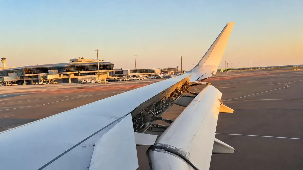
The wings carry significant aerodynamic and structural loads. Their principal structural elements include spars, ribs, structural skin, reinforcements, and the wing box.
Spars are among the primary structures that resist bending loads. Ribs help maintain the aerodynamic shape of the wing and transfer loads between different structural elements.
On many aircraft, sealed sections of the internal wing structure also serve as fuel tanks, creating what are commonly known as wet wings.
4. Wing-to-Fuselage Connection and Engine Mounting
The wing-to-fuselage connection must transfer substantial loads between these major aircraft structures. The center wing box and other reinforcing structures play an important role in distributing those forces.
On aircraft with engines mounted beneath the wings, each engine is generally attached through a pylon. The pylon has its own structural elements and transfers loads associated with engine weight, thrust, vibration, aerodynamic forces, and other operating conditions into the wing structure.
Amazon Recommended Products
AVIATION PICKS


5. Tail Structure
The aft section of an aircraft normally includes the vertical stabilizer, horizontal stabilizer, their associated flight-control surfaces, and the aft fuselage structure.
These structures must receive aerodynamic loads and transfer them into the fuselage. On many commercial aircraft, the aft fuselage or tail section also houses the Auxiliary Power Unit.
6. Windows and Windshields
Any opening in a pressurized fuselage interrupts the continuity of the structure, which means the surrounding areas must be appropriately reinforced.
Passenger windows use multiple panes and are designed to withstand operational loads and the pressure differential between the cabin and the outside atmosphere.
Flight-deck windshields use multilayer construction and, on many aircraft, incorporate electrical heating elements for anti-icing and anti-fogging functions.
7. Door Structure
Passenger doors, service doors, cargo doors, and emergency exits also create large openings in the fuselage and therefore require reinforced surrounding structures.
Door locking and indication systems are designed to prevent unsafe conditions. Depending on the aircraft design, mechanical features and pressure-related warnings help prevent or warn against improper door operation while a significant pressure differential exists between the inside and outside of the aircraft.
8. Landing Gear and Brakes
The landing gear must withstand substantial loads during landing, taxiing, braking, and ground maneuvering. A typical retractable landing gear assembly may include oleo-pneumatic shock struts, structural braces, hydraulic actuators, locking mechanisms, wheels, tires, brakes, and sensors.
Oleo-pneumatic shock struts normally use hydraulic fluid and compressed gas, commonly nitrogen, to absorb and dissipate landing energy.
On large commercial aircraft, wheel brakes are generally installed on the main landing gear. Modern systems may include multidisc carbon brakes, antiskid protection, autobrake functions, alternate braking modes, and overheat protection.
Nose landing gear should not be assumed to have wheel brakes. Many commercial aircraft have unbraked nose wheels.
9. APU — Auxiliary Power Unit
The Auxiliary Power Unit, or APU, is a small gas-turbine engine used to provide auxiliary power to the aircraft.
Depending on the aircraft design, the APU can supply electrical power, pneumatic power, or other forms of auxiliary energy.
Typical uses may include powering aircraft systems while the main engines are shut down, supporting cabin air conditioning, and providing pneumatic or electrical power needed during engine-start procedures.
10. Fuel System
On many commercial aircraft, the main fuel tanks are integrated into the wing structure. The fuel system may include main tanks, a center tank, pumps, valves, quantity sensors, fuel lines, vent systems, and surge tanks.
Internal wing ribs can also help reduce excessive fuel movement inside the tanks.
Some aircraft use fuel-tank flammability-reduction systems that introduce nitrogen-enriched air into the tank ullage, reducing the oxygen concentration and therefore the potential flammability of the fuel-vapor space.
This type of architecture should not be considered universal across all commercial aircraft.
11. Air Management
On many commercial aircraft, compressed air used by aircraft systems is extracted from engine compressor stages through the bleed-air system.
Bleed air may be used for functions such as cabin pressurization, air conditioning, pneumatic engine starting, anti-icing, and other pneumatic services.
This architecture is not universal. Aircraft with highly electrified systems may use electrically powered compressors instead of engine bleed air for certain functions.
12. Anti-Icing and Anti-Fogging Systems
Ice accumulation can change the aerodynamic shape of aircraft surfaces, increase drag, and interfere with aircraft components.
Anti-ice systems are designed to prevent or limit ice formation on protected areas.
Depending on the aircraft, wing leading edges, engine inlets, probes, and other areas may use hot air or electrical heating.
Flight-deck windshields may also incorporate electrical heating elements to protect against icing and reduce fogging.
13. Electrical System
Commercial aircraft electrical systems use multiple power sources and distribution paths. During normal operation, engine-driven generators may serve as the primary electrical sources.
Aircraft may also use APU generators, batteries, external ground power, and emergency power sources.
Electrical buses, contactors, control units, and protective devices distribute power throughout the aircraft and allow faults to be isolated while maintaining essential systems whenever possible.
14. Hydraulic System
Hydraulic systems can transmit substantial forces through relatively compact lines and actuators. For this reason, hydraulic power is widely used on transport-category aircraft.
Depending on aircraft design, hydraulic power may operate:
- primary flight-control surfaces;
- spoilers;
- flaps and slats;
- landing gear;
- wheel brakes;
- nose-wheel steering;
- thrust reversers.
Large commercial aircraft generally use more than one independent hydraulic circuit. This redundancy reduces the possibility that a single system failure will cause the loss of all critical hydraulic functions.
The number of hydraulic systems and the components powered by each circuit are aircraft-specific design features.
Amazon Recommended Products
AVIATION PICKS
15. Potable Water and Waste Systems
The potable-water system supplies water to locations such as lavatories and galleys. The system may include water tanks, pumps, valves, heaters, and distribution lines.
Lines exposed to low temperatures require appropriate protection against freezing.
Aircraft lavatories use dedicated waste-collection systems. On many commercial aircraft, pressure differential and vacuum systems help move waste from the toilet assemblies to a waste-storage tank.
16. Emergency Systems
Commercial aircraft emergency equipment provides multiple layers of protection for passengers and crew during abnormal or emergency situations.
Supplemental Oxygen
If significant cabin depressurization occurs, supplemental oxygen systems provide oxygen to occupants while the flight crew performs the required emergency procedures and descends to a safer altitude when necessary.
Depending on the installation, passenger oxygen may be supplied by chemical oxygen generators or other sources. Available oxygen duration is not universal and depends on the certified aircraft configuration.
Emergency Slides and Evacuation
Passenger doors and certain emergency exits may be equipped with inflatable evacuation slides.
When the system is properly armed for emergency operation, opening the applicable door or exit can initiate slide deployment and inflation.
RAT — Ram Air Turbine
Some aircraft are equipped with a Ram Air Turbine, or RAT. This small turbine can be deployed into the external airflow during specific emergency conditions.
Depending on the aircraft architecture, the RAT may provide hydraulic power, electrical power, or contribute to the generation of energy required to keep selected essential systems operating.
The correct technical term is RAT — Ram Air Turbine. Its exact function and the systems it supplies vary according to aircraft design.
Fire Detection and Extinguishing
Engines and APUs may incorporate fire-detection and fire-extinguishing systems.
Cargo compartments, equipment areas, and lavatories may also include smoke detectors and dedicated fire-protection equipment.
ELT — Emergency Locator Transmitter
The Emergency Locator Transmitter, or ELT, is designed to transmit a distress signal that can assist search-and-rescue services in locating an aircraft following certain emergency situations or accidents.
Flight Recorders and Aircraft Monitoring
The Flight Data Recorder, or FDR, records parameters related to aircraft operation. These data are especially important in accident investigations and technical analysis.
Modern aircraft may also incorporate aircraft health-monitoring and maintenance systems capable of recording faults, operational events, and other information used by maintenance personnel.
Quick Study Review
STRUCTURE
Fuselage → Pressurization → Wings → Wing-to-Fuselage Connection → Engine Mounting → Tail → Windows → Doors → Landing Gear
POWER AND AIRCRAFT SYSTEMS
APU → Fuel → Air Management → Anti-Icing and Anti-Fogging → Electrical → Hydraulic
SERVICES AND SAFETY
Water and Waste → Supplemental Oxygen → Evacuation → RAT → Fire Protection → ELT → Flight Recorders and Monitoring
Structures, pipes, mechanisms, and systems normally hidden beneath the aircraft skin become much easier to understand when viewed in three dimensions.
Watch the complete “Aircraft Structure and Systems in 3D” video for a detailed visual overview of the inside of a commercial aircraft.
▶ WATCH THE FULL VIDEOBibliographic References
- FEDERAL AVIATION ADMINISTRATION — FAA. Aviation Maintenance Technician Handbook — Airframe, FAA-H-8083-31B. Washington, D.C., 2023. Available from: Federal Aviation Administration .
- FEDERAL AVIATION ADMINISTRATION — FAA. Aviation Maintenance Technician Handbook — Powerplant, FAA-H-8083-32B. Washington, D.C., 2023. Available from: Federal Aviation Administration .
- FEDERAL AVIATION ADMINISTRATION — FAA. Pilot's Handbook of Aeronautical Knowledge, FAA-H-8083-25C — Chapter 3: Aircraft Construction. Washington, D.C., 2023. Available from: Federal Aviation Administration .
- FEDERAL AVIATION ADMINISTRATION — FAA. AC 25.981-1D — Fuel Tank Ignition Source Prevention Guidelines. Washington, D.C. Available from: Federal Aviation Administration .
- FEDERAL AVIATION ADMINISTRATION — FAA. 14 CFR Part 25 — Airworthiness Standards: Transport Category Airplanes. Certification standards applicable to transport-category airplanes.
Technical note: This material is intended for educational purposes and presents general aircraft-system principles. Specific configurations, limitations, capacities, maintenance procedures, and operating procedures must always be verified using the approved documentation for the applicable aircraft and manufacturer.