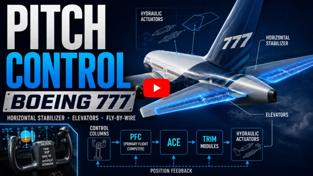
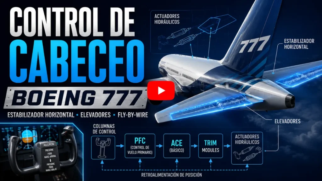
Pitch control allows the aircraft’s nose to be raised or lowered around its lateral axis. On transport aircraft, this control normally involves two different but integrated elements:
- the horizontal stabilizer, used primarily for longitudinal trim;
- the elevators, responsible for more immediate changes in attitude and flight path.
To illustrate this architecture in detail, the Boeing 777 system will be used as a reference. Although the number of computers, components, and control logic may vary among different aircraft, the principles presented here help explain how mechanical controls, sensors, computers, electronic units, and hydraulic power work together to provide longitudinal control in a modern aircraft.
Longitudinal control of the aircraft
Pitch is the movement of the aircraft around its lateral axis. When the nose rises, the aircraft has a positive pitch attitude. When the nose lowers, the aircraft has a negative pitch attitude.
This movement is controlled primarily by the elevators, which are installed on the trailing edge of the horizontal stabilizer. The stabilizer, in turn, changes the aircraft’s longitudinal balance and reduces the need to maintain continuous force on the control column.
Although they are installed within the same tail assembly, the stabilizer and elevators do not perform exactly the same function:
- the elevators produce rapid pitch responses;
- the stabilizer changes the aircraft’s longitudinal equilibrium condition;
- the elevators continuously follow commands from the pilot or autopilot;
- the stabilizer moves in a controlled manner to trim the aircraft.
When the aircraft is properly trimmed, it can maintain the desired attitude or flight path without requiring excessive continuous force on the controls.
Horizontal stabilizer and elevators
The horizontal stabilizer is an aerodynamic surface installed at the rear of the fuselage. On many commercial aircraft, its angle of incidence can be changed, which is why it is also referred to as a trimmable horizontal stabilizer.
The elevators are movable surfaces hinged to the trailing edge of the horizontal stabilizer. When they move, they change the aerodynamic force produced by the horizontal tail.
This change in force produces a pitching moment around the aircraft’s center of gravity, causing the nose to rise or lower.
In simplified terms:
- upward elevator deflection tends to produce a nose-up command;
- downward elevator deflection tends to produce a nose-down command.
The actual response depends on airspeed, aerodynamic configuration, center-of-gravity position, and the control laws used by the system.
Why does the stabilizer also need to move?
If only the elevators were used to continuously maintain a nose-up or nose-down condition, they could remain deflected for an extended period.
This condition could increase:
- aerodynamic drag;
- loads on the actuators;
- the force required on the controls;
- loads on the horizontal tail;
- the possibility of reducing the control authority available for additional commands.
The stabilizer changes the angle of incidence of the entire horizontal tail assembly relative to the airflow.
This creates a new equilibrium condition and allows the elevators to return to a position closer to neutral.
This is the fundamental purpose of longitudinal trim: adjusting the aircraft’s balance so that it can maintain the desired condition with less control effort.
Fly-by-wire architecture
In a conventional system, control-column movement may be transmitted to the flight-control surfaces through cables, rods, pulleys, and hydraulic mechanisms.
In a fly-by-wire system, the pilot’s movement is measured by sensors. The signals are sent to computers, which calculate the required response and command electrically controlled hydraulic actuators.
The architecture used as a reference includes:
- mechanically interconnected control columns;
- position transducers;
- four Actuator Control Electronics units;
- three Primary Flight Computers;
- hydraulic flight-control surface actuators;
- position-feedback systems;
- redundant power-supply and processing channels.
This architecture combines conventional cockpit controls with digital processing, continuous monitoring, and hydraulic power to move the flight-control surfaces.
Primary Flight Computers
The Primary Flight Computers, or PFCs, form the processing core of the primary flight-control system.
They receive information from several systems, including:
- pilot commands;
- autopilot commands;
- aircraft speed;
- altitude;
- attitude;
- accelerations;
- flap configuration;
- flight-control surface positions;
- inertial and aerodynamic data;
- control-system status.
Based on this information, the PFCs apply the control laws and calculate the appropriate position for the flight-control surfaces.
The use of three computers provides redundancy and fault tolerance. The system is designed to continue operating after certain processing, communication, or power-supply failures.
Actuator Control Electronics
The Actuator Control Electronics units, known as ACEs, provide the interface between analog or electromechanical components and the digital computers.
Their functions include:
- receiving signals from the transducers;
- converting analog signals into digital information;
- sending information to the PFCs;
- receiving calculated commands from the PFCs;
- converting digital commands into signals suitable for the actuators;
- monitoring the operation of connected components.
The system does not operate as a simple linear transmission path. It includes continuous monitoring, cross-channel comparison, and feedback of the actual flight-control surface positions.
How the horizontal stabilizer works
The horizontal stabilizer is moved by a dedicated trim system.
The pilot can command trim using switches installed on the control columns. These switches generate electrical signals corresponding to the desired direction:
- nose-up trim;
- nose-down trim.
The command is not sent directly to the stabilizer actuator.
First, the signal is sent to an ACE. The ACE interprets the input, performs the necessary conversion, and transmits the information to the PFC.
The computer evaluates the command and determines how the stabilizer should be moved.
In flight, the calculation may consider factors such as:
- airspeed;
- aircraft configuration;
- attitude;
- aerodynamic condition;
- active control mode;
- the permitted stabilizer movement rate.
On the ground, certain limitations that apply in flight may not be necessary. The system may therefore permit a higher movement rate during tests and inspections.
Stabilizer Trim Control Modules
After the PFC calculates the command, the information returns to the ACE.
The ACE sends signals to the Stabilizer Trim Control Modules.
These modules control the supply of hydraulic pressure to the stabilizer actuator.
Each module is associated with an independent hydraulic source. In the architecture used as a reference:
- one module uses the center hydraulic system;
- the other uses the right hydraulic system.
Separating the hydraulic sources increases redundancy and reduces the possibility that a single failure will cause the complete loss of the function.
The modules use valves to:
- release the actuator brakes;
- direct pressure to the hydraulic motors;
- determine the direction of movement;
- stop the movement;
- reapply the brakes.
Ball-screw actuator
The stabilizer is repositioned by an actuator assembly that uses a ball screw.
This mechanism converts the rotary movement of the hydraulic motors into linear movement.
The assembly includes:
- two hydraulic motors;
- differential gears;
- a ball screw;
- a translating mechanism;
- hydraulic brakes;
- structural connections to the stabilizer.
When a command is authorized, hydraulic pressure releases the brakes and drives both motors.
The motors drive the gear assembly, which rotates the ball screw. Movement of the mechanism changes the position of the structure connected to the stabilizer and alters its angle of incidence.
The use of two motors and independent hydraulic systems increases system availability.
Nose-up trim
During a nose-up trim command, the mechanism repositions the stabilizer to change the aerodynamic force produced by the horizontal tail.
In the architecture described here, the leading edge of the stabilizer moves downward.
This change in angle of incidence modifies the aerodynamic force at the tail and produces a moment that tends to raise the aircraft’s nose.
It is important to distinguish the physical movement of the surface from the effect produced on the aircraft.
Stabilizer movement describes the direction in which its edges move. The term “nose-up trim” describes the resulting effect on the aircraft’s attitude.
Therefore, a nose-up command does not necessarily mean that the leading edge of the stabilizer also moves upward.
Stopping stabilizer movement
When the pilot releases the trim switch, the movement command is removed.
The trim modules:
- stop hydraulic flow to the motors;
- stop rotation of the ball screw;
- reapply the brakes;
- hold the stabilizer in the position reached.
The brakes prevent uncommanded stabilizer movement under aerodynamic loads.
The stabilizer remains in the new position until another trim command is made or an automatic function determines that a new adjustment is required.
Stabilizer position indication
Stabilizer position is measured by transducers.
These devices provide information for:
- the flight-control computers;
- system monitoring;
- cockpit indication;
- discrepancy detection;
- comparison between commanded and actual position.
Position feedback allows the system to confirm whether the stabilizer reached the commanded angle.
Alternate trim control
In addition to the electrical command provided by the control-column switches, an alternate means of controlling longitudinal trim is available.
This system uses a lever mechanically connected to the trim modules by cables.
When the lever is moved:
- the cables move;
- control rods operate the manual valves;
- the modules release their respective brakes;
- hydraulic pressure drives the motors;
- the stabilizer moves in the selected direction.
When the lever is released, it returns to the neutral position. The manual valves close, movement stops, and the brakes are reapplied.
This path allows the stabilizer to be commanded without depending on the normal sequence of signals between the switches, ACEs, and PFCs, although it still uses hydraulic power and the actuator mechanism.
How the control columns work
The elevators are commanded primarily by movement of the control columns.
When the column is pulled rearward, the system receives a command corresponding to nose-up movement. When it is pushed forward, the system receives a command corresponding to nose-down movement.
The captain’s and first officer’s control columns are mechanically interconnected.
This interconnection allows the movement made by one pilot to be perceived by the other and provides an indication of the direction and intensity of the applied command.
Control-column breakout mechanism
The connection between the columns includes a separation device known as a breakout mechanism.
Under normal conditions, this mechanism keeps both columns connected. When one column moves, the other follows.
If one column becomes mechanically jammed, a rigid connection could prevent the other pilot from applying any elevator command.
In this situation, applying sufficient force to the free column can cause the mechanism to separate.
After separation, the unjammed column can be moved independently, preserving an additional means of longitudinal control.
Feel and centering system
In a fly-by-wire system, the aerodynamic forces acting on the elevators are not transmitted directly to the pilot’s hands.
For this reason, the system must artificially produce:
- resistance to movement;
- a sense of control loading;
- a tendency to return to neutral;
- changes in required effort based on the flight condition.
The control columns are connected to elevator feel units.
When the pilot moves the column, the movement works against springs and internal mechanisms. When the control is released, energy stored in the springs helps return the column to neutral.
These units help provide a predictable relationship between column displacement, applied force, and aircraft response.
Control-column transducers
Control-column movement is not transmitted directly to the elevators by cables.
The displacement is measured by transducers connected to the control-column mechanism and the feel units.
These transducers generate analog signals proportional to the control position.
- the pilot moves the column;
- the connected mechanisms also move;
- the transducers measure the displacement;
- the signals are sent to the ACEs;
- the ACEs convert the signals;
- the PFCs calculate the required elevator position;
- the command returns to the ACEs;
- the ACEs control the hydraulic actuators.
The PFC does not necessarily convert a specific amount of column displacement into one fixed elevator angle.
The relationship may vary according to:
- airspeed;
- altitude;
- configuration;
- control mode;
- aerodynamic loading;
- active protections;
- system condition.
Elevator actuators
Each elevator is moved by two Power Control Units, or PCUs.
Because there are two elevators, four PCUs are used:
- two for the left elevator;
- two for the right elevator.
The PCUs are electrically controlled hydraulic actuators.
They receive signals from the ACEs and use hydraulic pressure to generate the force required to move the surfaces.
The actuators are installed in the rear section of the horizontal stabilizer and are connected to the elevators.
Supplying the actuators from different hydraulic systems helps ensure that the loss of a single source does not necessarily cause the complete loss of elevator control.
Manual elevator control
During a manual command:
- the pilot moves the control column;
- the transducer measures the displacement;
- the ACE converts the input;
- the PFC calculates the response;
- the ACE commands the PCUs;
- the PCUs move the elevators;
- the actuator transducers measure the position;
- the information returns to the system.
This feedback loop provides closed-loop control.
The computer continuously compares the commanded position with the actual measured position.
If a difference exists, the actuator command is adjusted until the surface reaches the calculated position.
Precision and synchronization
Because each elevator has more than one actuator, the system must prevent two PCUs from attempting to position the same surface differently.
Excessive differences could produce high internal loads on the structure and on the actuators themselves.
The system monitors:
- flight-control surface position;
- hydraulic pressure;
- the response of each actuator;
- agreement between channels;
- movement rate.
This information is used to keep the actuators synchronized and to detect failures.
Autopilot control
When the autopilot is engaged, the pitch command originates from the automatic flight system.
The autopilot computer determines the change required to:
- maintain an altitude;
- capture a selected altitude;
- follow a vertical flight path;
- control airspeed in certain modes;
- perform an approach;
- perform other automatic functions.
The command is sent to the PFC, which calculates the required elevator deflection and, when applicable, the stabilizer adjustment.
- the PFC sends the command to the ACE;
- the ACE controls the PCUs;
- the elevators move;
- the transducers confirm the position;
- the system continuously adjusts the response.
The final hydraulic actuation is similar to that of a manual command. The main difference is the source of the request.
Control-column backdrive
During autopilot operation, the control columns may also move.
This movement is produced by backdrive actuators connected to the control-column torque tubes.
The system:
- engages the actuator clutch;
- energizes the motor;
- moves the control-column mechanism;
- positions the columns according to the automatic command.
This allows the pilots to observe and feel the command being made by the autopilot.
When the system commands the nose to rise, the columns may move rearward. When it commands the nose to lower, they may move forward.
Movement of the cockpit controls provides a visual and tactile indication of automatic system operation.
Return to neutral after an automatic command
When the autopilot command ends:
- the backdrive motor stops;
- the clutch disengages;
- the actuator stops applying force;
- the feel and centering units reposition the columns.
This return occurs in coordination with elevator position and the stabilizer trim condition.
The column can return to neutral even if the stabilizer remains in a new trim position.
This occurs because the stabilizer maintains the new longitudinal equilibrium condition, allowing the elevators to return to a position closer to neutral.
Integration between the stabilizer and elevators
Pitch control does not depend on only one surface.
The elevators and stabilizer work together:
- the elevators produce the immediate response;
- the stabilizer reduces the need for prolonged elevator deflection;
- the PFCs coordinate both functions;
- the ACEs interface with the actuators;
- the transducers confirm the movements;
- the autopilot can command the same system;
- the cockpit controls provide feedback to the pilots.
During a sustained change to a climbing flight path, for example:
- the elevators initiate the nose movement;
- the aircraft begins changing its attitude;
- the system calculates the required trim;
- the stabilizer is repositioned;
- the load carried by the elevators decreases;
- the columns can return to a more neutral position;
- the aircraft remains balanced in the new condition.
Why does the stabilizer not replace the elevators?
Although the stabilizer also produces pitching moments, it does not replace the elevators.
The stabilizer:
- moves in a more controlled manner;
- has a significant trimming effect;
- changes the aircraft’s longitudinal equilibrium;
- is not intended to independently reproduce every rapid control input.
The elevators:
- respond more quickly;
- produce immediate changes in flight path;
- continuously follow control commands;
- provide precise control during maneuvers and landings.
Separating the control and trim functions provides a rapid response without sacrificing aerodynamic efficiency.
Differences between ground and in-flight operation
System behavior may differ between ground and in-flight operation.
On the ground:
- aerodynamic loads are low;
- higher trim rates may be permitted;
- certain protections may not be required;
- the system may respond more directly during testing.
In flight:
- movement rates may be limited;
- the system considers aerodynamic loads;
- aircraft configuration affects the commands;
- the control laws determine the relationship between column movement and elevator deflection;
- the stabilizer is coordinated with longitudinal balance;
- protections and stability-augmentation functions may be active.
For this reason, movement observed during a ground check does not necessarily represent the movement rate or behavior of the surfaces under every flight condition.
System redundancy
Redundancy is achieved through a combination of different features:
- three PFCs;
- four ACEs;
- multiple transducers;
- different communication channels;
- two actuators per elevator;
- independent hydraulic sources;
- two trim modules;
- two hydraulic motors in the stabilizer system;
- normal and alternate controls;
- continuous position monitoring.
Redundancy does not simply mean duplicating components. Its purpose is to prevent a single failure from causing the complete loss of longitudinal control.
Other measures include:
- physical segregation;
- independent power sources;
- cross-channel comparison;
- degraded operating modes;
- failure monitoring;
- isolation of faulty components.
Summary of stabilizer operation
- the pilot operates the trim switch;
- the ACE receives the signal;
- the signal is converted and sent to the PFC;
- the PFC calculates the command;
- the information returns to the ACE;
- the ACE commands the trim modules;
- the modules release the brakes;
- hydraulic pressure drives the motors;
- the motors rotate the ball screw;
- the stabilizer changes position;
- the transducers report its position;
- when the command ends, the motors stop and the brakes are reapplied.
Summary of elevator operation
- the pilot moves the control column;
- the other column follows the movement;
- the transducers measure the displacement;
- the ACE converts the signals;
- the PFC calculates the elevator position;
- the command returns to the ACE;
- the PCUs receive the signals;
- hydraulic pressure moves the elevators;
- the PCU transducers measure the position;
- the system corrects any difference;
- when the column is released, the feel units help return it to neutral.
Sequence during autopilot operation
- the autopilot computer calculates a pitch command;
- the command is sent to the PFC;
- the PFC calculates the elevator position;
- the ACE commands the PCUs;
- the elevators move;
- position feedback confirms the movement;
- the autopilot activates the backdrive actuators;
- the columns move to represent the command;
- when the maneuver ends, the backdrive system disengages;
- the columns return to the position corresponding to the trimmed condition.
Reference sources
FAA — Federal Aviation Administration. Boeing 777 Flight Standardization Board Report, Revision 12.
AAIB — Air Accidents Investigation Branch. Report on the accident to Boeing 777-236ER, G-YMMM, at London Heathrow Airport.
NASA. Computers Take Flight: A History of NASA’s Pioneering Digital Fly-By-Wire Project.
International Council of the Aeronautical Sciences — ICAS. Innovative Aspects of the Boeing 777 Development Program.
KLEEMANN, E. The Development of a Civilian Fly-by-Wire Flight Control System. ICAS, 2000.
NIEDERMEIER, D. et al. Fly-by-Wire Augmented Manual Control. ICAS, 2012.
FAA — Federal Aviation Administration. Airframe and Powerplant Mechanics General Handbook.