Electrical System

To explain this system, we will use the Boeing 737 MAX 8, also known as the Boeing 737-8, as a reference. The purpose is not to turn this document into a technical manual for the aircraft, but to use this model as a practical example so the reader can understand how the electrical system works in a modern commercial airplane.

Some details may vary depending on the aircraft configuration, the airline, the installed equipment, the applicable technical documentation, and maintenance updates. For that reason, this material should be understood as an educational explanation, not as an operational procedure or maintenance instruction.

The electrical system is one of the most important systems in a commercial aircraft. It provides power for instruments, lights, navigation, communication, computers, electronic controls, cabin equipment, warning systems, and many other functions that are essential for safe operation.

What is the aircraft electrical system?

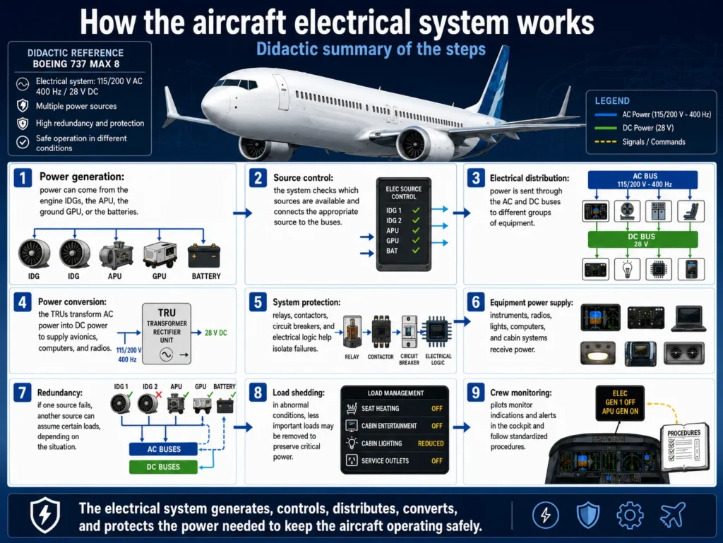
The electrical system is responsible for generating, distributing, converting, protecting, and monitoring the electrical power used by the aircraft. In simple terms, it works like the airplane’s power network.

This network receives power from different sources, sends that power to distribution buses, converts alternating current into direct current when necessary, and protects equipment against faults, overloads, or improper power supply.

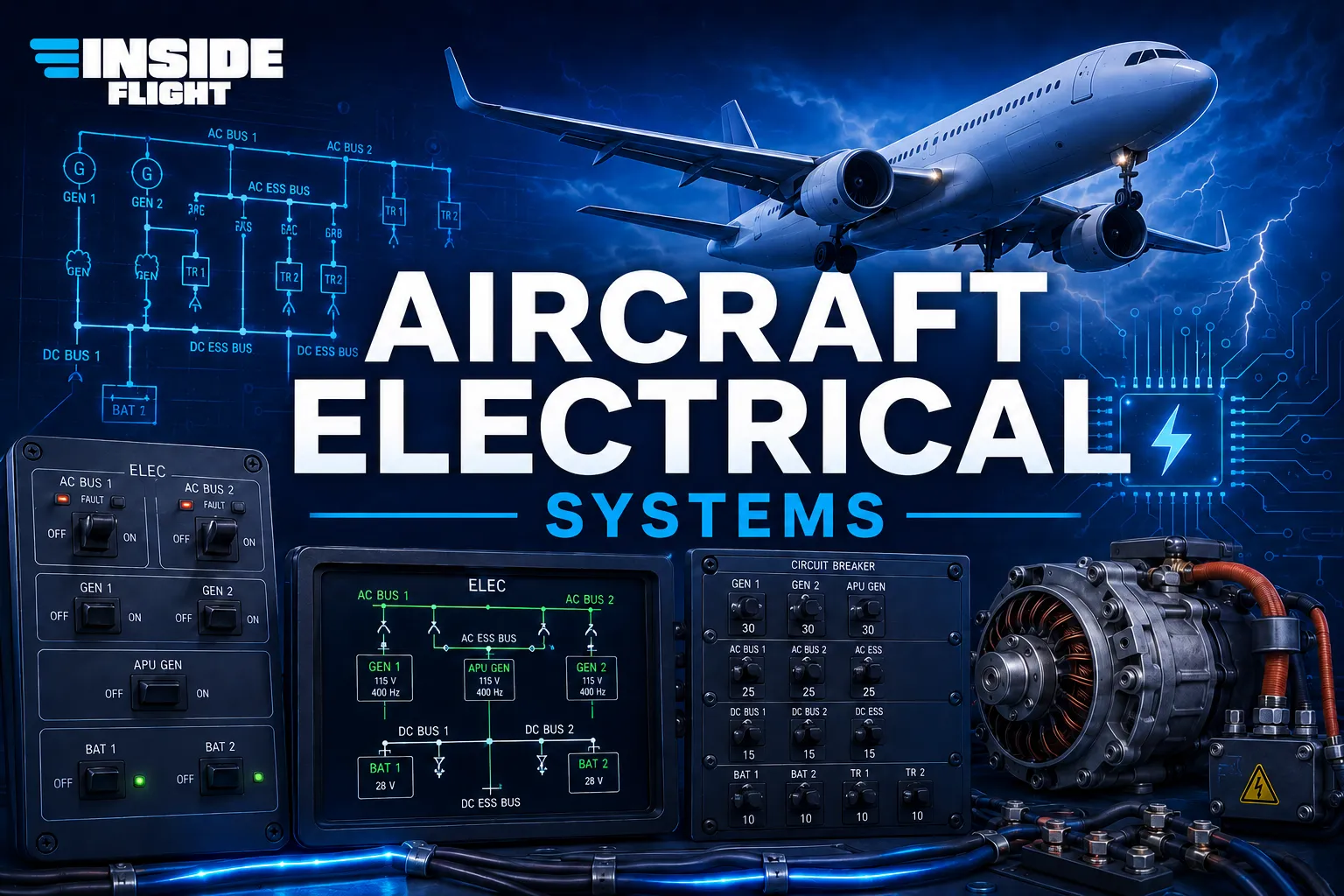
On the Boeing 737 MAX 8, the general logic of the system follows an architecture that includes main power sources, alternative sources, batteries, conversion units, AC and DC buses, protection systems, and cockpit indications.

Electrical power sources

The aircraft does not depend on only one source of electrical power. It can be powered by engine-driven generators, the APU, external ground power, and batteries. Each source has a specific role during aircraft operation.

1. IDGs — Integrated Drive Generators

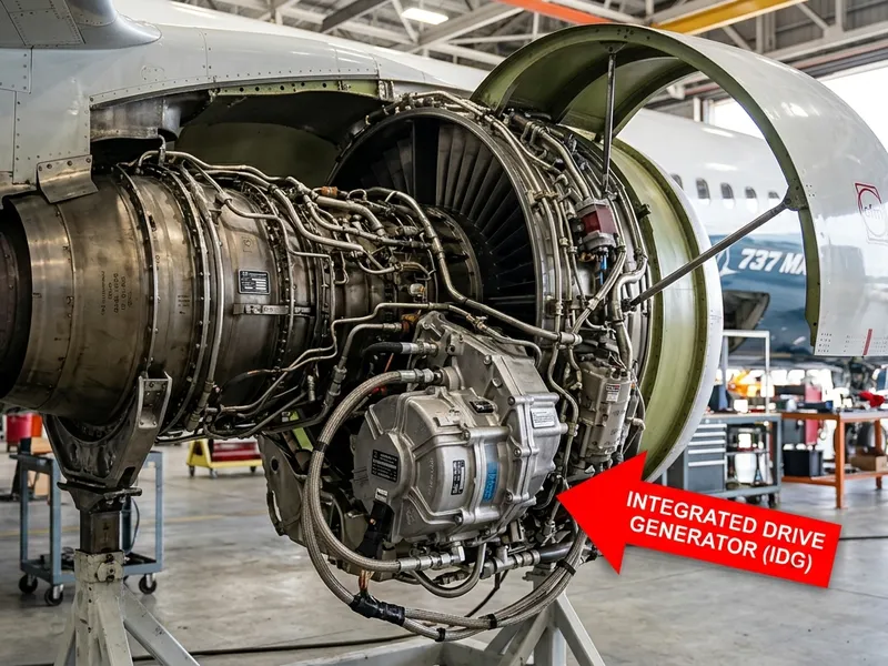
During normal flight, the main source of electrical power on the Boeing 737 MAX 8 comes from the IDGs, or Integrated Drive Generators. Each engine has its own IDG. The left engine drives IDG 1, and the right engine drives IDG 2.

The IDG converts the mechanical rotation of the engine into alternating current electrical power. The main aircraft electrical system commonly uses three-phase 115/200-volt AC power at 400 Hz. This higher frequency is common in aircraft because it allows electrical equipment to be smaller and lighter compared with lower-frequency systems.

The term “integrated drive” means that the generator has an integrated drive mechanism that helps maintain the proper electrical frequency even when engine speed changes. In simple terms: the engine changes power settings during flight, but the electrical system still needs to deliver stable power.

For a didactic explanation, IDG 1 normally supplies the left side of the aircraft, while IDG 2 normally supplies the right side. This separation helps maintain independence between both sides and improves system redundancy.

Position on the engine: the IDGs are located on the lower side area of the accessory gearbox, generally around the 4 or 5 o’clock position when looking at the engine from the front.

External access: to physically access them, mechanics need to open the lower engine cowlings, known as the Fan Cowl Doors.

Quantity: there are two IDGs on the aircraft — one on Engine 1, under the left wing, and one on Engine 2, under the right wing.

Integrated Drive Generator installed on the right engine of a Boeing 737, showing its position within the engine assembly.
Integrated Drive Generator on the right engine of a Boeing 737

2. APU — Auxiliary Power Unit

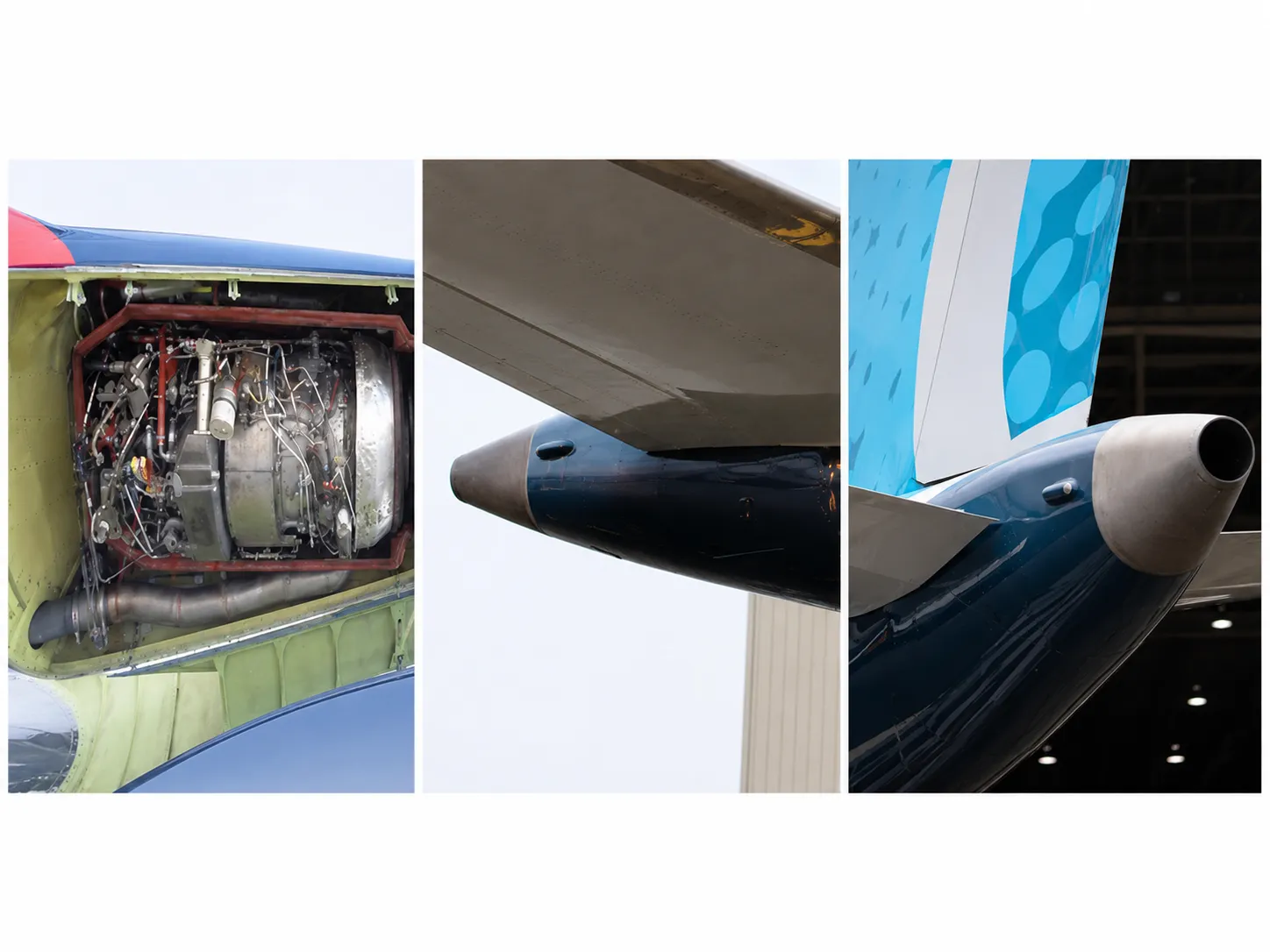
The APU is a small turbine engine installed in the tail of the aircraft. It is not used to produce thrust for flight, but it can provide electrical power and pneumatic air.

On the ground, the APU allows the cockpit, communication systems, lighting, cabin equipment, and other systems to be powered before the main engines are started. It can also supply pneumatic air for air conditioning and engine start, depending on the operation.

Under certain conditions, the APU may also be used as an alternative source of electrical power in flight. This is important because, if an engine generator fails, the APU can provide backup power, within the applicable operational limits and procedures.

The APU is located in the rear section of the aircraft fuselage and is isolated from the rest of the cabin by a titanium firewall for safety. The air inlet door is located on the upper right side of the fuselage, just ahead of the tail cone. Hot exhaust gases exit through the opening at the very end of the tail. That is why, at airports, it is often possible to see exhaust coming from the tail of the aircraft.

Aircraft APU, showing the rear fuselage compartment where the unit is installed.
APU — left image: open fuselage compartment

3. GPU — Ground Power Unit

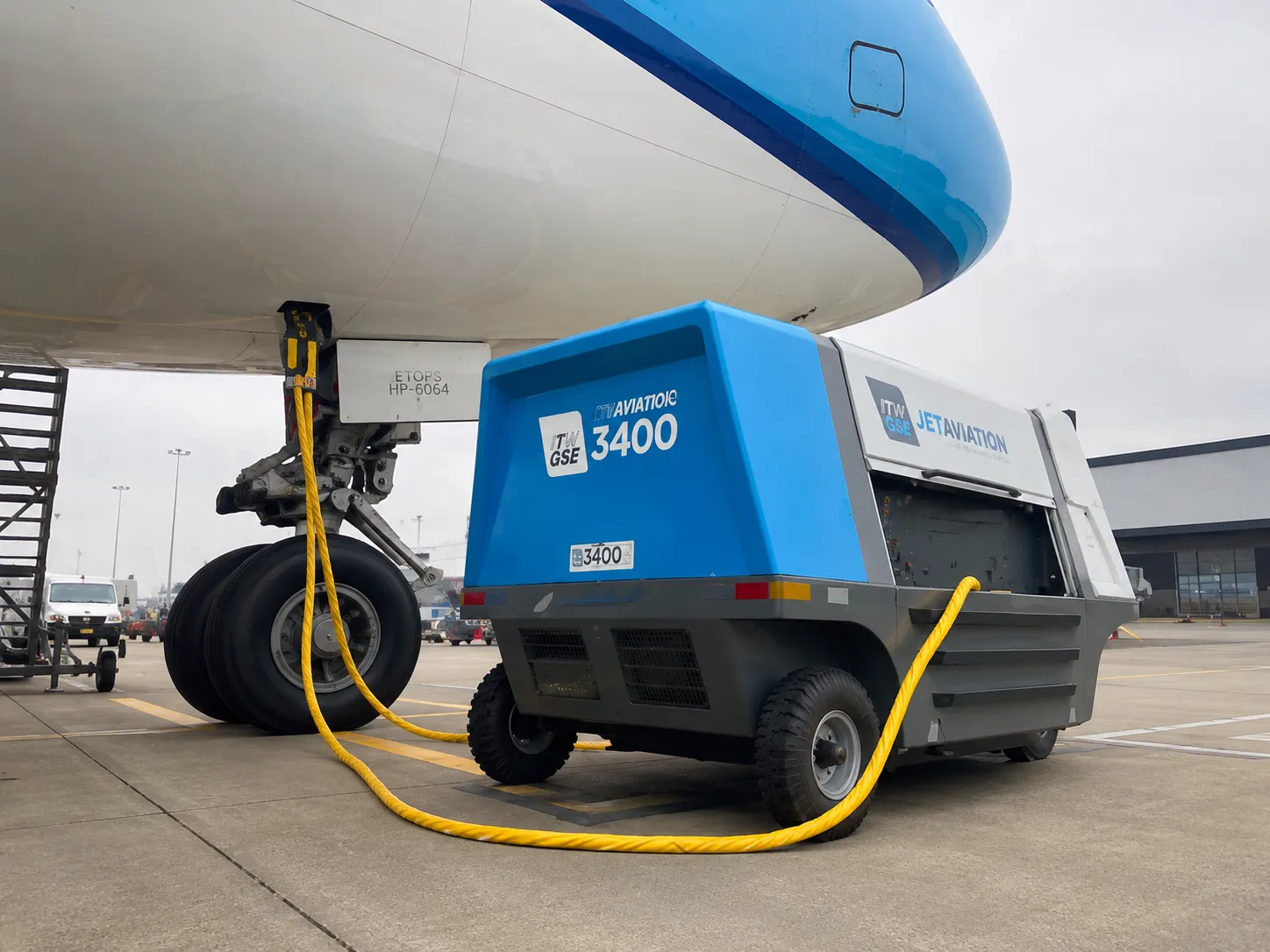
When the aircraft is parked at the airport, it can receive electrical power from an external ground source called a GPU — Ground Power Unit — also known as external power.

The GPU is connected to the aircraft by a cable and allows systems to remain powered without using the APU. This saves fuel, reduces noise, lowers emissions on the ramp, and supports maintenance, boarding, and preflight preparation.

In a typical operation, the aircraft may initially be powered by the GPU. Then the crew starts the APU, disconnects external power, and after engine start, the engine generators become the main source of electrical power.

Ground Power Unit connected to a commercial aircraft on the ramp, supplying electrical power while the aircraft is on the ground.

4. Batteries

Batteries are limited-capacity power sources, but they are extremely important. They can supply essential circuits, allow initial electrical power-up, and keep critical systems available in specific situations.

In the context of the 737 MAX, there are batteries intended for main and standby support functions. The most important didactic point is to understand that the batteries are not designed to power the entire aircraft for a long time. They exist to preserve essential functions for limited periods and allow the crew to keep critical instruments and resources available during abnormal conditions.

In a severe loss of electrical generation, the batteries and standby buses become essential for maintaining the minimum required functions, such as key flight instruments, communication, certain indications, and critical safety resources.

Alternating current and direct current

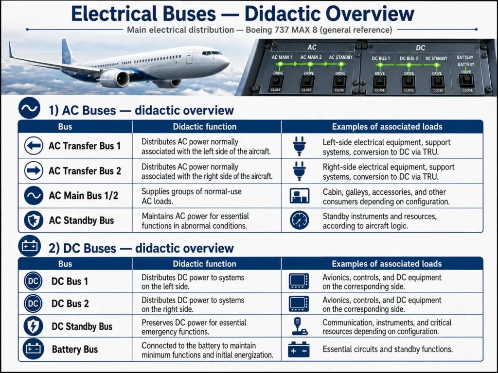
An aircraft electrical system works with two main types of electrical power: alternating current, known as AC, and direct current, known as DC.

AC power supplies many main systems, especially higher-power equipment. DC power supplies many avionics, control circuits, computers, radios, indication systems, and standby functions.

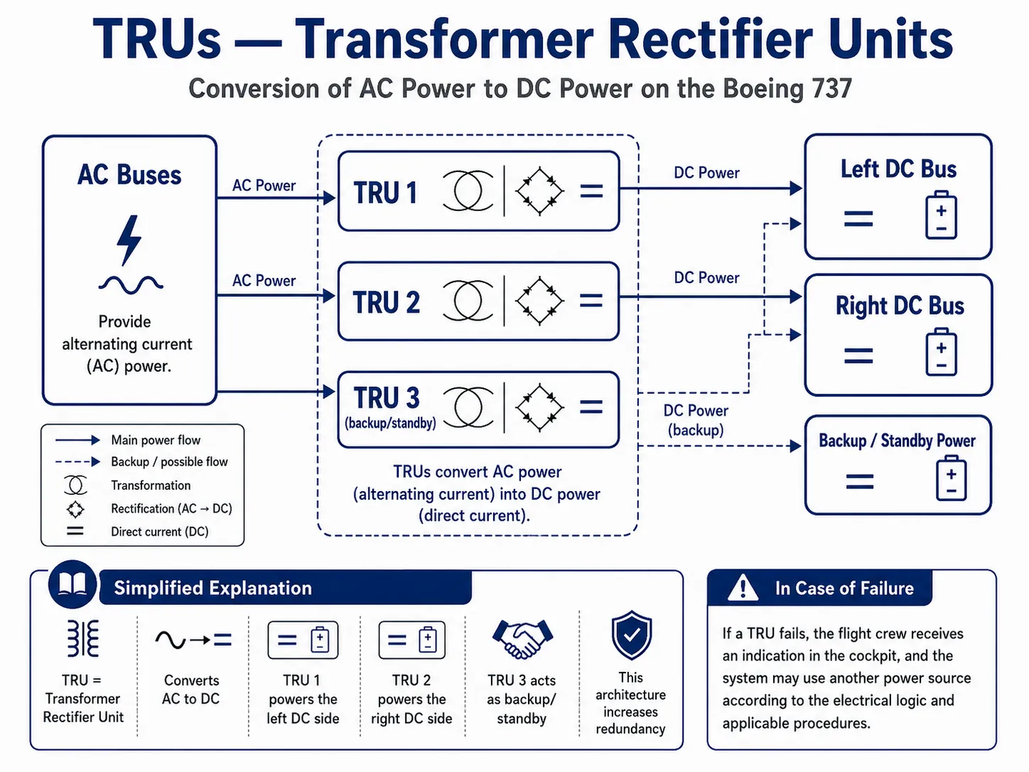
Because a large part of the generated power is AC, while many aircraft components require DC, the aircraft uses conversion units called TRUs.

TRUs — Transformer Rectifier Units

TRUs, or Transformer Rectifier Units, convert AC power into DC power. In simple terms, they take alternating current from the AC buses and deliver direct current to the DC buses.

On the Boeing 737, this can be explained didactically as follows: one TRU supplies the left DC side, another TRU supplies the right DC side, and a third TRU acts as a support or standby source under certain conditions. This architecture helps maintain redundancy between the two sides of the aircraft.

If a TRU fails, the crew receives an indication in the cockpit, and the system may use another power source according to the aircraft’s electrical logic and the applicable procedures.

Schematic summary of TRU operation, showing the conversion of AC power into DC power in the aircraft electrical system.
Schematic summary of TRU operation.

Note: this content is educational and introductory. It does not replace official manuals, Boeing technical documentation, FAA publications, certified training, airline operating procedures, or approved maintenance instructions.

Electrical Buses

An electrical bus is like an organized power distribution line. Instead of connecting each piece of equipment directly to the generator, electrical power reaches the bus and, from there, is distributed to groups of systems.

This organization allows the system to manage power more efficiently, separate loads by priority, transfer power between sources, and isolate faults without compromising the entire aircraft.

On the Boeing 737, the system is commonly explained through AC buses, DC buses, main buses, transfer buses, standby buses, and buses connected to the battery.

Electrical Overhead Control Panel

This is the physical panel located on the ceiling of the Boeing 737 MAX flight deck. The upper central section, with its rotary selectors and digital displays, directly monitors the voltage and amperage of each electrical bus, such as Gen 1, Gen 2, APU, and Main Battery.

Power Transfer Between Sources

The aircraft must be able to switch electrical power sources safely. On the ground, it may start by using external power from a GPU. Then, it may switch to the APU. After engine start, the IDGs become the main source of electrical power.

This transfer is performed by contactors, relays, control units, and electrical logic. The goal is to connect the proper power source to the correct bus and prevent incompatible sources from feeding the same load at the same time.

In simple terms, the aircraft selects, or allows the crew to connect, the best available power source while keeping the systems powered and protecting the electrical network.

AC Sources Do Not Operate in Parallel

An important technical point is that the aircraft’s AC power sources should not feed the same load in parallel. This prevents electrical conflict between sources, phase differences, instability, and possible damage to the system.

For this reason, the electrical logic uses transfer and isolation devices. One source may power one side, another source may power the other side, and under certain conditions one source may supply both transfer buses. However, the system is designed to prevent two sources from feeding the exact same load at the same time.

How the System Works During Each Phase of Operation

On the Ground — Aircraft Parked

When the aircraft is parked on the ramp, external power can supply basic systems. This allows lights, instruments, some cabin systems, and technical equipment to remain powered without starting the APU.

During maintenance, the GPU is especially useful because it allows technicians to work on electrical and avionics systems with lower fuel consumption and less noise.

On the Ground — Flight Preparation

During flight preparation, the crew powers up the flight deck, checks systems, configures panels, and prepares the aircraft for engine start. The power source may be the GPU or the APU, depending on airline procedures and airport availability.

The APU may be started to provide electrical power and pneumatic air. This makes it possible to operate air conditioning, cabin systems, and prepare for engine start.

Engine Start

During engine start, electrical power and pneumatic air must be managed properly. The APU can provide air for engine start and electrical power for the systems that need to remain energized.

After the engines stabilize, the engine-driven generators take over as the main source of electrical power. The APU can then be shut down if it is no longer needed.

Normal Flight

In flight, the normal condition is for the aircraft to be powered by the engine-driven generators. Each side of the aircraft receives power through its own bus logic and conversion system.

The TRUs continuously convert AC power into DC power, allowing avionics, computers, radios, and control circuits to receive the proper type of electrical power.

The crew monitors the electrical system from the flight deck, but much of the electrical management happens automatically through internal system logic.

Approach, Landing, and Arrival

During approach and landing, the electrical configuration normally remains stable. Lighting, navigation, communication, landing gear, flaps, displays, and computers continue to depend on electrical power.

After landing and parking, the aircraft may return to external GPU power or APU power, allowing the main engines to be shut down.

Electrical Panel in the Flight Deck

In the flight deck, the electrical system controls and indications are mainly located on the overhead panel, above the pilots’ heads.

Through this panel, the crew can check available power sources, connect or disconnect generators, monitor battery indications, verify external power, monitor buses, and respond to alerts.

It is important to understand that pilots do not control every wire in the aircraft. They manage power sources, check indications, and follow procedures. The internal system logic handles much of the management, protection, and transfer process.

Electrical System Protections

The electrical system must protect itself against abnormal conditions. An electrical fault cannot be allowed to spread freely through the aircraft or compromise systems that are still operating correctly.

For that reason, the system uses protective devices, isolation logic, and crew alerts. If a power source develops a problem, it can be disconnected. If a circuit has a fault, it can be isolated. If there is an overload, selected loads can be removed.

  • Overload protection: prevents a power source or circuit from being demanded beyond its limit.
  • Short-circuit protection: isolates affected circuits to prevent greater damage.
  • Faulty source disconnection: removes a problematic generator or power source from the electrical network.
  • Load transfer: allows systems to be powered by another available source when applicable.
  • Flight deck alerts: inform the crew about abnormal conditions and support the execution of the proper procedures.

Load Shedding — Prioritizing Electrical Loads

Load shedding is the controlled removal of less important electrical loads in order to preserve power for essential systems. This concept is especially important during an electrical emergency.

To a passenger, this may look like a serious malfunction: reduced cabin lighting, screens turning off, power outlets not working, or limited air conditioning. For the system, however, it may mean that electrical power is being preserved for what truly matters: instruments, communication, navigation, and control.

High Priority — Critical Functions

  • Essential flight instruments.
  • Required VHF communication.
  • Transponder and surveillance functions.
  • Essential navigation and indication systems.
  • Controls and computers required for safe operation.

Lower Priority — Loads That May Be Removed First

  • Galleys and onboard service equipment.
  • Cabin entertainment systems.
  • Passenger power outlets, USB ports, and accessories.
  • Non-essential lighting.
  • Some cabin comfort loads, depending on the condition and system logic.

Failures and Emergency Scenarios

Generator Failure in Flight

If an engine-driven generator fails in flight, the situation is usually manageable. The system can isolate the affected source and use another available source to keep the required buses powered.

Depending on the condition, the other generator may supply additional loads, or the APU may be started to provide an alternate source of electrical power. The crew receives indications and follows the applicable checklist.

Severe Loss of AC Power Generation

A total or severe loss of AC power generation is a rare and very serious condition. In this scenario, the goal is not to maintain full cabin comfort, but to preserve the safe operation of the aircraft.

The batteries and standby buses become central to the situation. Non-essential loads may be removed automatically or by procedure. The crew uses the QRHQuick Reference Handbook — to try to restore electrical generation and maintain control, navigation, and communication.

Relationship With Other Aircraft Systems

The electrical system supports almost every other system on the aircraft. Without electrical power, many aircraft systems simply would not operate.

System Relationship With the Electrical System
Avionics Displays, computers, FMC, EFIS, TCAS, GPWS, and the transponder depend on electrical power.
Communication Radios, audio panels, data link, and interphone systems require electrical power.
Navigation Sensors, receivers, computers, and displays depend on electrical power.
Hydraulic System Some pumps and electrical controls depend on the aircraft’s electrical buses.
Fuel System Pumps, indications, and controls use electrical power.
Cabin Lighting, passenger address, entertainment, power outlets, and some service equipment depend on electrical power.
APU The APU needs electrical power for start, control, and monitoring.

The Difference Between Electrical Generation and Distribution

Electrical generation is the process of producing or supplying power. This power can come from the IDGs, the APU, a GPU, or the batteries.

Electrical distribution is the path that power follows until it reaches the equipment. It passes through buses, contactors, relays, circuit breakers, control units, and converters.

In simple terms, the source generates or supplies power; the distribution system sends that power to the right places; and the protection system helps prevent a fault from causing greater damage.

Why the Electrical System Matters to Passengers

To passengers, the electrical system is almost invisible. It shows up in simple things such as lights, screens, power outlets, announcements, air conditioning, and emergency lighting.

Behind all of that, however, there is a technical network that powers essential flight safety functions. Without proper electrical power, pilots could lose instruments, radios, displays, computers, alerts, and several support systems.

That is why the electrical system is designed with redundancy, protection, and load prioritization. The goal is to make sure that, even during failures, the aircraft keeps power available for the systems that matter most for safe flight.

Step-by-Step Educational Summary

  1. Power generation: electrical power can come from the engine IDGs, the APU, an external GPU on the ground, or the batteries.
  2. Source control: the system checks which sources are available and connects the proper source to the electrical buses.
  3. Electrical distribution: power is sent through AC and DC buses to different groups of equipment.
  4. Power conversion: the TRUs convert AC power into DC power for avionics, computers, and radios.
  5. System protection: relays, contactors, circuit breakers, and electrical logic help isolate faults.
  6. Equipment power supply: instruments, radios, lights, computers, and cabin systems receive electrical power.
  7. Redundancy: if one source fails, another source may take over certain loads, depending on the situation.
  8. Load shedding: during abnormal conditions, less important loads may be removed to preserve power for critical systems.
  9. Crew monitoring: pilots monitor indications and alerts in the flight deck and follow standardized procedures.

On the Boeing 737 MAX 8, the electrical system is responsible for supplying, distributing, converting, protecting, and monitoring the power used by several aircraft systems. It can receive power from the engine generators, the APU, external ground power, and the batteries.

Its function is to keep essential and operational equipment powered in a safe, reliable, and controlled way. It is not just a comfort system for the cabin; it is a fundamental infrastructure for avionics, communication, navigation, indications, controls, and operational safety.

Educational Note

This content is educational and introductory. It does not replace official manuals, Boeing technical documentation, FAA publications, certified training, airline procedures, or guidance from qualified professionals.