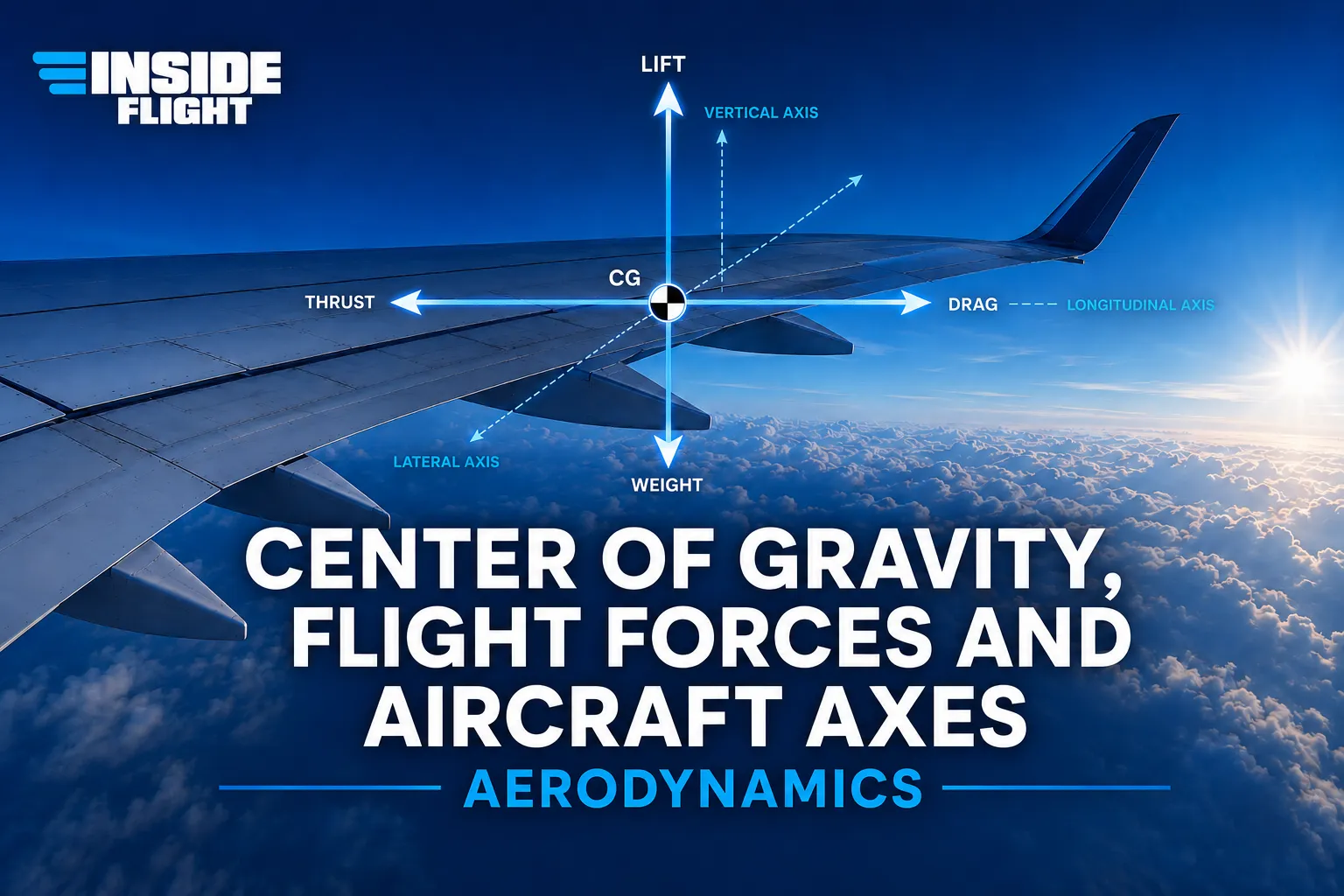
An airfoil is a surface designed to produce a useful reaction when it moves through the air. In aviation, that reaction may be the lift that keeps the aircraft in the air, the thrust produced by a propeller, or even the forces used to stabilize and control the aircraft during flight.
The wing is the best-known example of an airfoil, but it is not the only one. Propeller blades, the horizontal stabilizer, the vertical stabilizer, and some control surfaces can also work as airfoils. The central idea is simple: the part has a shape capable of organizing the airflow and turning that airflow into a useful force.
For anyone working in aircraft maintenance, this subject is essential. Dents, deformation, ice, dirt, uneven paint, improper gaps, or poorly performed repairs can change the shape of the airfoil and disturb the airflow. When that happens, aerodynamic efficiency may decrease and flight safety may be affected.
An airfoil is a shape designed to turn airflow into a useful force.
In technical terms, an airfoil is a surface designed to produce a desired aerodynamic reaction when there is relative motion between that surface and the air. In simpler language, it is a shape created to “work with the air” and generate a force that supports flight.
As the aircraft moves, air flows around its wings, stabilizers, and control surfaces. This air does not simply pass around them randomly. It is accelerated, deflected, locally compressed, and organized by the shape of the airfoil. The result of this interaction is the creation of aerodynamic forces.
In the case of a wing, the most important force is lift. In the case of a propeller, the blades also have an airfoil shape, but their purpose is to produce thrust by pushing air backward and helping move the aircraft forward.
Term explained: Airfoil
A surface with an aerodynamic shape, designed to produce a useful force as it moves through the air. A wing produces lift; a propeller blade helps produce thrust; stabilizers and control surfaces help with stability and control.
Simple example: Think of a wing: it is not just a flat plate. Its shape is designed to guide the air and generate lift.
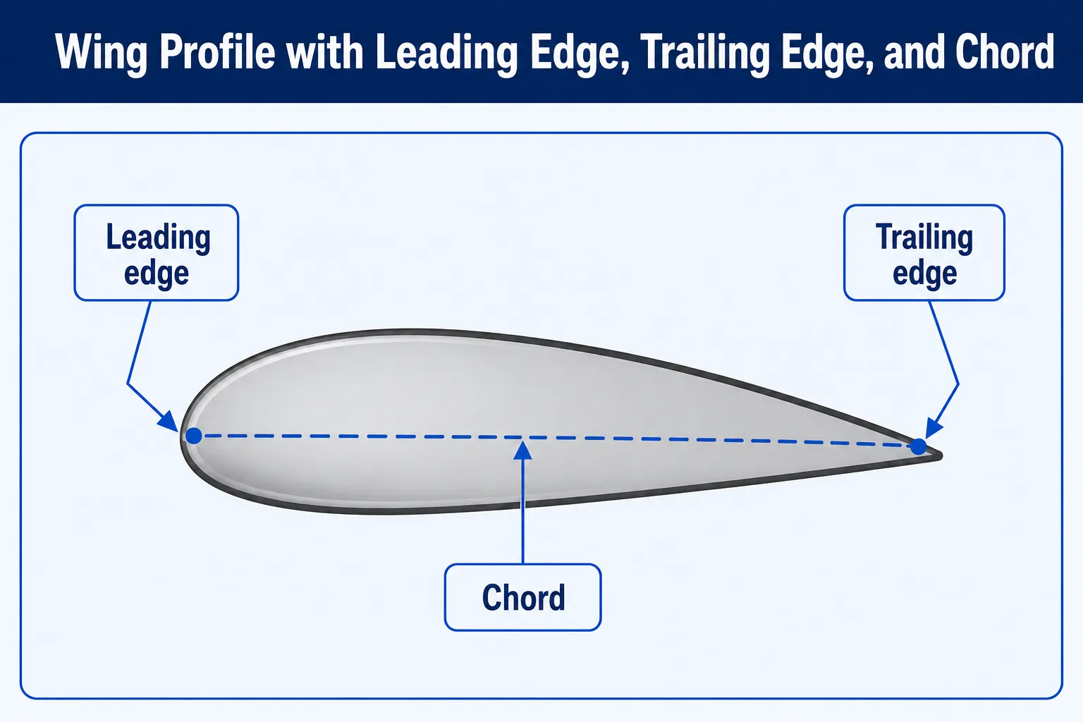
Before understanding angle of attack, it is important to know three basic references on a wing section: the leading edge, the trailing edge, and the chord.
The leading edge is the front part of the airfoil, meaning the first area of the wing that meets the air during motion. The trailing edge is the rear part, where the airflow that passed over and under the wing meets again.
The chord is an imaginary straight line connecting the leading edge to the trailing edge. It is not a physical part installed in the wing. It is a geometric reference used to measure angles and explain the aerodynamic behavior of the wing section.
Term explained: Wing Chord
An imaginary line drawn from the leading edge to the trailing edge of the airfoil. It serves as a reference for measuring angle of attack and angle of incidence.
Simple example: Imagine a straight line connecting the front tip of the wing to the rear tip. That line is the chord.
The chord is a reference line used to study angle of attack and angle of incidence.
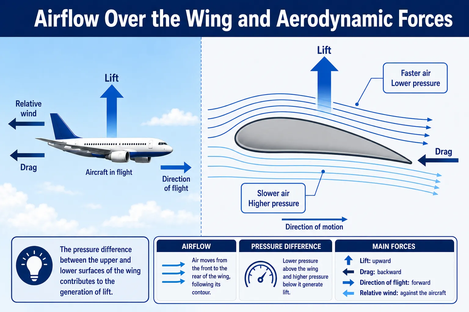
On a conventional wing, the upper surface usually has more curvature than the lower surface. This difference in shape affects the path and speed of the air flowing around the wing.
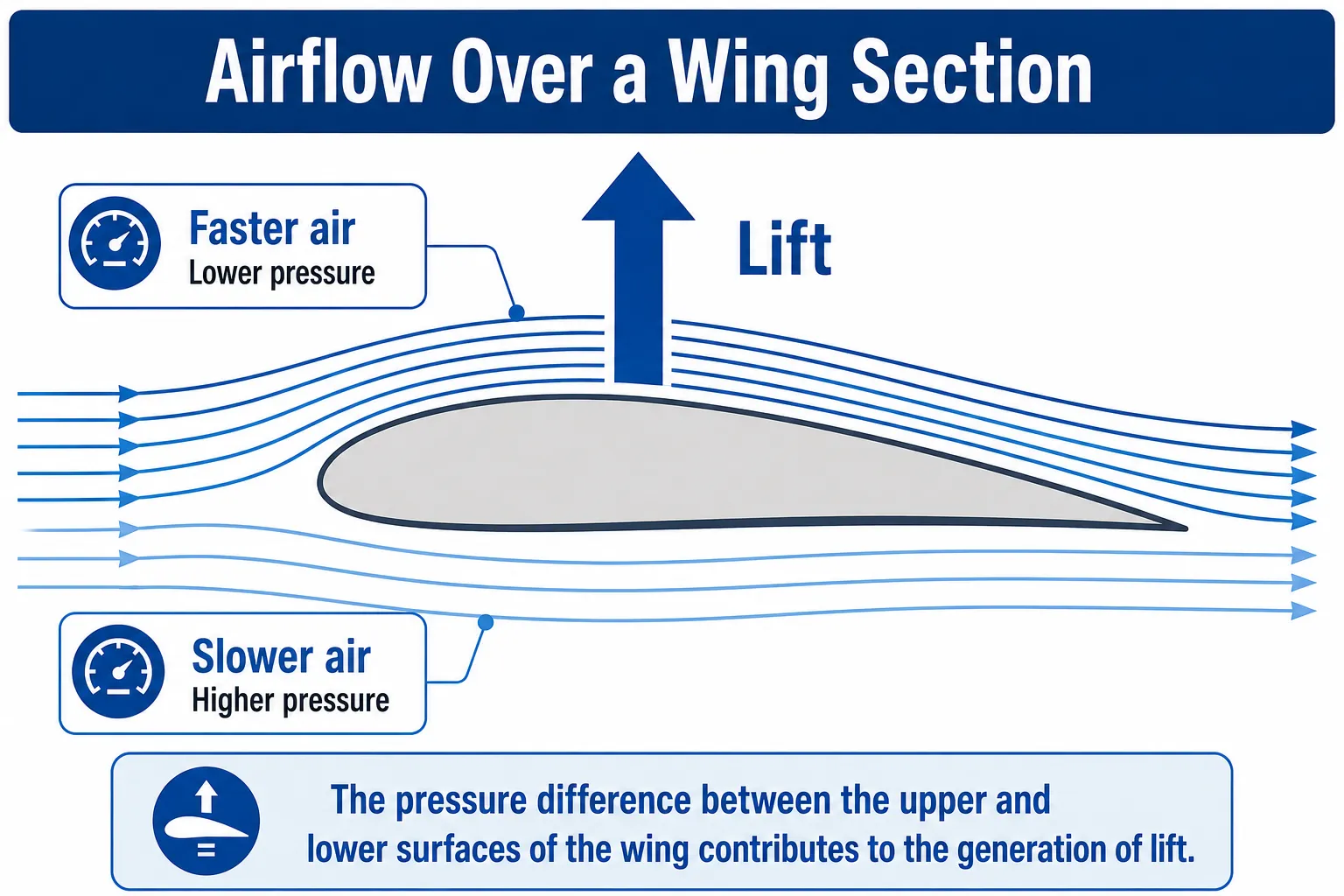
When air passes over the upper surface of the wing, it tends to move faster. According to Bernoulli’s principle, when the speed of a fluid increases, its pressure decreases. Because air behaves as a fluid, this rule also applies to airflow over the wing.
At the same time, the pressure below the wing remains relatively higher. As a result, a pressure difference develops between the lower and upper surfaces. This pressure difference helps push the wing upward, producing lift.
It is important to understand that Bernoulli’s principle explains an important part of lift, but it is not the only explanation. The wing also deflects part of the airflow downward. According to Newton’s third law, if the wing pushes air downward, the air reacts by pushing the wing upward. In practice, lift involves pressure difference, airflow deflection, angle of attack, and airspeed.
Pressure difference and downward airflow deflection both contribute to lift.
A pressure difference that seems small can produce a very large force when it acts over a wide area. This is a key point for understanding lift. The wing does not depend on one single point of force; pressure acts across the entire surface.
Imagine a wing with a small pressure difference between the lower and upper surfaces. When that difference is multiplied by the total wing area, the result can be large enough to support an entire aircraft. This is why, in aerodynamics, small pressure values can represent large forces when they are applied over large areas.
The exact amount of lift depends on several factors: airfoil shape, airspeed, air density, wing area, and angle of attack. If any of these factors changes, lift can change as well.
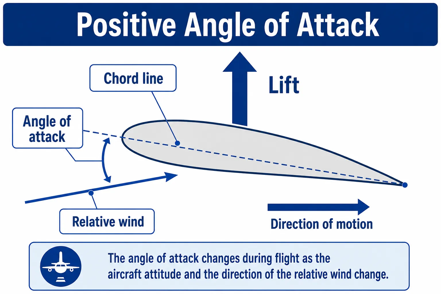
Angle of attack is one of the most important concepts in flight theory. It is the angle formed between the wing chord line and the direction of the relative wind.
Relative wind is the airflow that passes the aircraft in the opposite direction of its motion. Even if the air is still relative to the ground, it appears to approach the wing from the front because the aircraft is moving. This direction of airflow relative to the wing is what matters when determining angle of attack.
When the pilot changes the aircraft’s attitude, especially by raising or lowering the nose, the angle of attack may increase or decrease. This angle directly affects lift and drag.
Term explained: Angle of Attack
The angle between the wing chord and the relative wind. It changes during flight and has a major influence on lift, drag, and stall risk.
Simple example: When the aircraft’s nose rises too much relative to the airflow, the angle of attack increases.
Angle of attack is measured between the wing chord and the relative wind.
During flight, small aerodynamic forces act at many points along the wing surface. Each small area of the wing experiences a force with its own magnitude and direction. To simplify the analysis, all of these small forces can be represented by one resultant force.
The point where this resultant force acts is called the center of pressure. In simple terms, it is the aerodynamic point where the total lift effect can be considered to act.
The center of pressure does not always stay in the same place. It moves along the chord as the angle of attack changes. In many airfoils, when angle of attack increases, the center of pressure tends to move forward; when the angle decreases, it tends to move aft.
This movement matters because it changes the aerodynamic moments acting on the wing and can influence aircraft stability and control.
Term explained: Center of Pressure
The point on the airfoil where the resultant aerodynamic force can be considered to act. It moves when angle of attack changes.
Simple example: Instead of analyzing thousands of small pressure forces over the wing, we represent the total effect as one resultant force acting at the center of pressure.
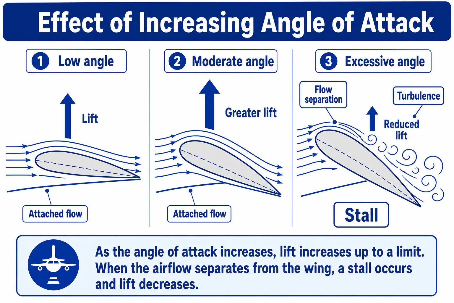
Within certain limits, increasing angle of attack increases lift. This happens because the wing interacts more strongly with the airflow, increasing the pressure difference and deflecting more air downward.
However, there is a limit. If the angle of attack keeps increasing, the air can no longer follow the upper surface of the wing smoothly. The flow separates, turbulence develops, and the low-pressure region above the wing becomes disorganized.
This limit is called the critical angle of attack. When it is exceeded, a stall occurs. In a stall, the wing loses much of its ability to generate lift, and drag increases rapidly.
It is important to point out that a stall does not depend only on the indicated airspeed shown on the instrument panel. Stall is directly related to angle of attack. An aircraft can stall at different speeds depending on weight, configuration, bank angle, flap position, and other flight conditions.
Term explained: Stall
A significant loss of lift caused mainly by airflow separation over the wing when the critical angle of attack is exceeded.
Simple example: It is not simply “flying too slowly.” The key point is that the wing has reached an angle of attack that is too high to keep airflow organized.
Increasing angle of attack increases lift up to the limit of the critical angle.
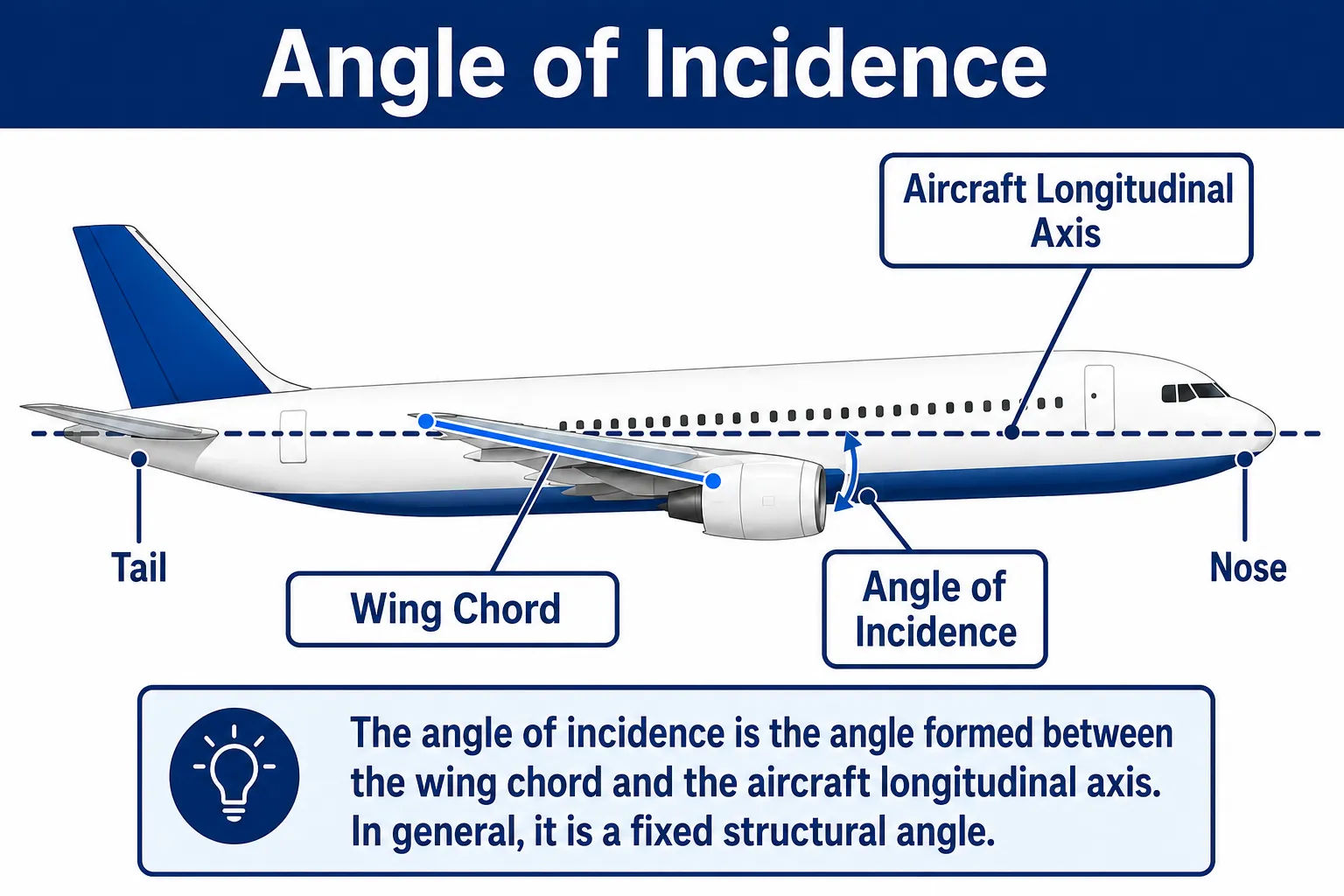
Angle of incidence is different from angle of attack. It is the angle formed between the wing chord and the aircraft’s longitudinal axis. The longitudinal axis is an imaginary line running from the nose to the tail of the airplane.
On most aircraft, the angle of incidence is fixed because it is part of the structural design of the wing installation. This means it does not change continuously during flight, unlike angle of attack.
If the wing’s leading edge is higher than the trailing edge relative to the longitudinal axis, the angle of incidence is positive. If it is lower, the angle is negative. On conventional aircraft, the wing is usually installed with a small positive angle of incidence to help produce lift during normal flight conditions.
Term explained: Angle of Incidence
The angle between the wing chord and the aircraft’s longitudinal axis. It is normally defined by design and remains fixed.
Simple example: While angle of attack changes during flight, angle of incidence is a feature of how the wing is installed on the aircraft.
Angle of incidence is a structural feature of the wing installation.
Wing area, also called planform area, is the total wing surface considered for aerodynamic purposes. In practical terms, it is like looking at the aircraft from above and observing the area covered by the wings.
Lift and drag are related to wing area. If the area increases and all other factors remain the same, lift tends to increase, but drag may also increase. For this reason, wing design must balance efficiency, performance, weight, and structural strength.
Aircraft designed to operate at lower speeds or on shorter runways generally need greater lift capability. This can be achieved through an appropriate wing area and through high-lift devices such as flaps and slats.
The shape of the airfoil determines how air flows around the wing. A very thin profile may produce low drag, but it may not generate enough lift in some conditions. A very thick profile may generate good lift at low speed, but it may also increase drag.
For that reason, wing shape depends on the purpose of the aircraft. A training aircraft, an airliner, a glider, a supersonic fighter, and a cargo aircraft do not use exactly the same type of wing because each one has different requirements for speed, lift, range, stability, and structural strength.
Wing efficiency is often analyzed by comparing lift to drag. The more lift a wing can produce with less drag, the more efficient the airfoil is for that flight condition.
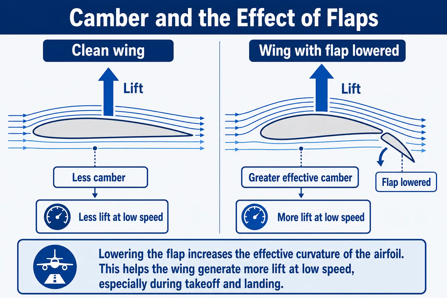
Camber is the curvature of the airfoil. It indicates how much the wing profile curves in relation to the chord line. On a conventional wing, the upper surface usually has a more pronounced curvature than the lower surface.
Greater camber generally helps increase lift, especially at lower speeds. However, it can also increase drag. For this reason, camber must be selected according to the aircraft’s mission and the desired performance.
When flaps are extended, they temporarily change the shape of the wing. In many cases, they increase the camber and the effective wing area, allowing the wing to produce more lift during takeoff and landing.
Term explained: Camber
The curvature of the airfoil in relation to the chord line. Greater camber tends to improve lift, especially at low speeds, but it can also increase drag.
Simple example: When the flap is lowered, the wing becomes more “curved.” This increases camber and helps the aircraft generate more lift during takeoff and landing.
Flaps change the wing shape and increase effective camber.
Wing aspect ratio is a geometric relationship mainly connected to wingspan and mean chord. In simple terms, it compares how “long and narrow” or “short and wide” a wing is.
Wings with a higher aspect ratio, such as those on gliders, are usually more efficient at producing lift with less induced drag. Wings with a lower aspect ratio may be more suitable for aircraft that need greater structural strength, maneuverability, or operation in specific flight regimes.
However, increasing aspect ratio is not always the best solution. A very long wing may require a stronger and heavier structure, and it may also create operational limitations. The final design must balance aerodynamics, structure, weight, cost, and the aircraft’s intended purpose.
Term explained: Wing Aspect Ratio
A measurement that relates the wingspan to the mean chord. Long, narrow wings have a higher aspect ratio; short, wide wings have a lower aspect ratio.
Simple example: Gliders usually have long, narrow wings because they need high aerodynamic efficiency.
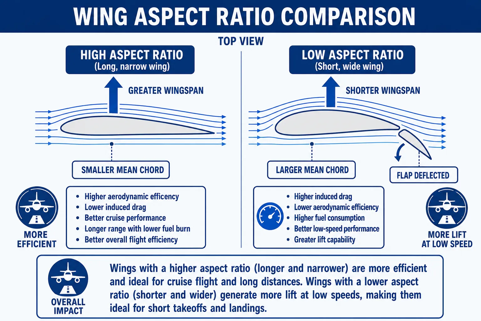
Aspect ratio affects aerodynamic efficiency and induced drag.
For an aircraft maintenance technician, an airfoil should not be seen only as a theoretical shape from a textbook. It is a real surface installed on the aircraft, and it must keep its correct geometry in order to work as designed.
A small deformation on a wing, a misaligned control surface, ice buildup, poor paint finish, an improperly repaired panel, or an out-of-limit gap can disturb the airflow. Depending on the affected area, this may increase drag, reduce lift, cause vibration, change control response, or compromise safety.
That is why visual inspections, measurements, adjustments, control surface balancing, gap checks, and proper repair procedures are directly connected to aircraft aerodynamics.
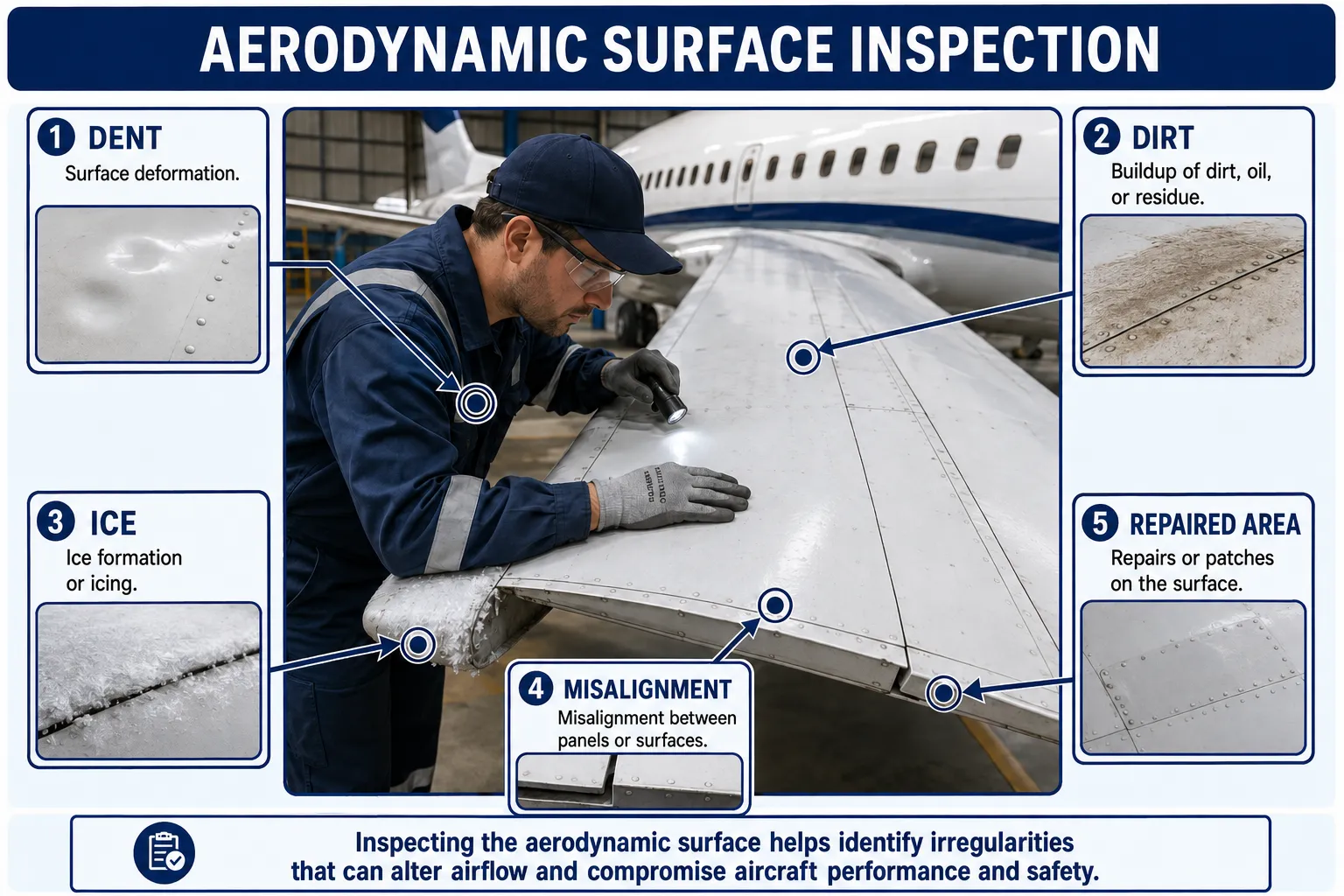
The physical condition of aerodynamic surfaces directly affects flight safety.
Airfoils are fundamental to flight because they turn the relative motion of air into useful forces. The wing produces lift, the propeller helps produce thrust, and other aerodynamic surfaces contribute to stability and control.
To understand how airfoils work, it is necessary to understand terms such as leading edge, trailing edge, chord, camber, angle of attack, angle of incidence, center of pressure, wing area, and aspect ratio. These concepts explain why wing shape is so important and why small changes can produce major effects in flight.
In summary, aerodynamics is not just theory. It appears in everyday aviation practice, especially in maintenance. Keeping aerodynamic surfaces clean, aligned, undamaged, and within technical limits is an essential part of aircraft safety and performance.