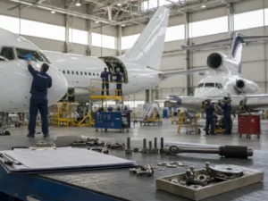

An aircraft structure is the assembly of parts responsible for providing shape, strength, and support for the other installed systems. It must withstand loads on the ground, in flight, during maneuvers, in turbulence, during takeoff and landing, and throughout normal aircraft operation.
In the study of the aircraft airframe, the structure includes elements such as the fuselage, wings, empennage, landing gear, nacelles, fairings, and flight control surfaces. This subject also covers structural stresses, construction methods, materials, and the precautions required to preserve the aircraft’s structural integrity.
Note: this content is intended for educational and introductory purposes. It does not replace official maintenance manuals, approved technical documentation, certified training, manufacturer instructions, or regulations issued by aviation authorities.
Figure 1 — Main external structural assemblies of a fixed-wing aircraft.
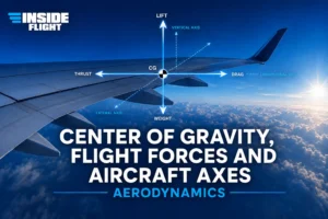
The aircraft structure does more than simply “give the airplane its shape.” It transfers loads, supports components, maintains aerodynamic alignment, and protects internal areas. In flight, lift generated by the wings, aircraft weight, maneuvering forces, and aerodynamic loads act on different parts of the airframe.
For this reason, each structural part is designed to perform according to its specific function. A wing spar, for example, serves a very different purpose from a removable fairing. A movable flight control surface also has different requirements from a fuselage frame or a skin panel.
Loads applied to an aircraft can produce different types of structural stress. In practice, these stresses usually occur in combination. A wing in flight, for example, may simultaneously experience bending, torsion, tension, compression, and shear in different areas.
Figure 2 — Basic structural stresses acting on an aircraft structure.
| Stress | Simplified Description | Where It May Occur |
|---|---|---|
| Tension | Tends to stretch the component. | Cables, tie rods, and areas subjected to elongation. |
| Compression | Tends to shorten or compress the component. | Spars, struts, ribs, and structural supports. |
| Shear | Tends to make one surface slide relative to another. | Rivets, bolts, overlapping sheets, and structural joints. |
| Bending | Combines tension and compression on opposite sides of the same member. | Wings, spars, and members subjected to distributed loads. |
| Torsion | Tends to twist the structure around its axis. | Wings, fuselage, empennage, and aerodynamic surfaces. |
The fuselage is the central part of the aircraft. It houses the crew, passengers, cargo, equipment, plumbing, wiring, and numerous systems. It also provides attachment points for the wings, empennage, landing gear, and, in some designs, the engines.
There are several fuselage construction methods. Truss construction may be found in light aircraft. In modern aircraft, semi-monocoque construction is very common because it combines the skin and internal members to distribute loads more effectively.
| Type | Main Concept | Technical Note |
|---|---|---|
| Truss | A structure made of tubes or members joined in strong geometric arrangements. | Commonly associated with light, classic, or simpler aircraft designs. |
| Monocoque | The outer skin carries most of the structural load. | It depends heavily on the integrity of the structural shell. |
| Semi-Monocoque | Combines skin, frames, longerons, and stringers. | Commonly used in modern aircraft because it distributes loads efficiently. |
To ensure that an inspection or repair is performed at the correct location, aircraft use reference systems established by the manufacturer. Rather than identifying an area in general terms, technical documentation may use stations, lines, and reference planes to precisely locate a region of the fuselage, wing, nacelle, or another assembly.
| Reference | Purpose |
|---|---|
| Fuselage Station | Identifies positions along the length of the fuselage. |
| Buttock Line | Identifies lateral positions relative to the aircraft centerline. |
| Waterline | Identifies vertical positions relative to a reference plane. |
| Wing Station | Identifies points along the wing span. |
| Nacelle Station | Helps identify areas related to the engine compartment. |
The wing is one of the aircraft’s most important structures. Its primary aerodynamic function is to generate lift, but structurally it must also withstand significant bending and torsional loads. In many modern aircraft, the wing may also contain fuel, hydraulic systems, wiring, high-lift devices, and flight control surfaces.
Figure 3 — Basic wing structure with spars, ribs, stringers, and skin.
The main wing members are the spars, ribs, stringers, and skin. The spars carry a large portion of the primary loads. The ribs maintain the aerodynamic shape. The stringers help distribute loads and prevent skin deformation. In many aircraft, the skin is not merely an external covering; it also contributes to structural strength.
Primary longitudinal wing members associated with resistance to bending and other structural loads.
Maintain the aerodynamic shape and help transfer loads between the skin and spars.
Increase local stiffness and help prevent skin buckling or deformation.
Forms the wing’s external surface and, in stressed-skin structures, also carries part of the load.
Wing configuration depends on the aircraft’s mission, operating speed, weight, stability requirements, and desired performance. A light training aircraft, for example, normally does not use the same wing geometry as a transport jet or a supersonic aircraft.
| Configuration | General Characteristics |
|---|---|
| Straight Wing | Provides good efficiency at low speeds and is common on light and training aircraft. |
| Swept Wing | Commonly used on jets, especially higher-speed aircraft. |
| Delta Wing | Triangular in shape and associated with high-speed operation and high structural rigidity. |
| Variable-Sweep Wing | Allows the wing geometry to change according to the phase of flight and operational requirements. |
Flight control surfaces allow the aircraft to be controlled about its three primary axes. Primary control surfaces are directly associated with roll, pitch, and yaw control. Auxiliary surfaces modify lift, drag, or trim, or assist during specific phases of flight.
Figure 4 — Main primary and secondary flight control surfaces.
| Surface | Primary Function | Related Axis |
|---|---|---|
| Ailerons | Control aircraft roll. | Longitudinal axis. |
| Elevators | Control pitch movement. | Lateral axis. |
| Rudder | Controls yaw. | Vertical axis. |
| Flaps | Increase lift and drag during specific phases of flight. | Not a primary axis-control surface. |
| Spoilers | Reduce lift and increase drag; they may also assist with lateral control. | Roll assistance and energy management. |
Important Point: ailerons normally move in opposite directions to create a lift difference between the wings. Flaps, on the other hand, generally move together to change lift and drag.
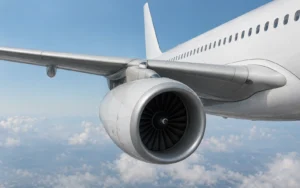
Nacelles are aerodynamic enclosures that house engines and related components. They may include removable cowling panels, structural members, a firewall, supports, and the engine mount.
Fairings improve aerodynamic airflow and provide access for inspection and maintenance. The engine mount performs an important structural function because it supports the powerplant and transfers its loads to the aircraft structure. The firewall separates the engine compartment from other areas in accordance with applicable design and certification requirements.
The empennage is the assembly located at the tail section of the aircraft. It contributes to stability and control by combining fixed and movable surfaces. On many airplanes, this assembly includes the horizontal stabilizer, elevator, vertical stabilizer, rudder, and tail cone.
| Component | General Function |
|---|---|
| Horizontal Stabilizer | Contributes to longitudinal stability. |
| Elevator | A movable surface associated with pitch control. |
| Vertical Stabilizer | Contributes to directional stability. |
| Rudder | A movable surface associated with yaw control. |
| Tail Cone | Closes the aft section of the fuselage and contributes to aerodynamic streamlining. |
The landing gear supports the aircraft’s weight on the ground, absorbs landing loads, and allows movement during taxi, takeoff, and landing. It may be fixed or retractable, depending on the aircraft. Retractable landing gear reduces drag in flight.
| Arrangement | General Characteristics |
|---|---|
| Conventional | Uses main wheels and a tailwheel. It requires greater attention during ground operations. |
| Tricycle | Uses main wheels and a nose wheel. It is very common on modern aircraft. |
| Tandem | Uses wheels aligned longitudinally beneath the fuselage and is used in specific applications. |
Honeycomb construction is a type of sandwich structure. It combines outer face sheets with an internal cellular core to provide high stiffness at low weight. This construction may be used in panels, surfaces, and components where a high strength-to-weight ratio is important.
Although lightweight and efficient, this type of structure requires special attention during inspections and repairs. Delamination, moisture intrusion, contamination, and internal damage may not be as visible as damage in a conventional metal sheet. Therefore, evaluations must follow the methods and limits specified in the applicable technical documentation.
Helicopters follow many structural principles similar to those of fixed-wing aircraft, but they also have important differences. The main rotor, tail rotor, transmissions, and dynamic loads create specific design, inspection, and maintenance requirements.
In many helicopters, the structure includes a main cabin and a tail boom. Depending on the model, the tail boom may support directional-control components such as the tail rotor, drive shafts, stabilizers, and gearboxes. As with airplanes, materials and attachment methods vary according to the design and technical documentation.
For aircraft maintenance professionals, understanding aircraft structures is essential for interpreting drawings, locating inspection areas, identifying damage, understanding repair limits, and recognizing the function of each assembly. A crack, corrosion, a loose rivet, deformation, or an improperly installed fairing may indicate a condition that requires technical evaluation.
In aircraft maintenance, structural assessment must never be based solely on visual appearance or personal judgment. The correct decision depends on the applicable documentation, manufacturer-defined limits, approved procedures, and airworthiness requirements.
Technical Summary: the aircraft structure consists of assemblies that work together to carry loads, maintain aerodynamic shape, protect internal systems, and enable safe operation. The fuselage, wings, empennage, landing gear, nacelles, and flight control surfaces must be understood as parts of an integrated structural system.
Editor’s References and Research Materials:
Federal Aviation Administration — Aviation Maintenance Technician Handbook – Airframe, FAA-H-8083-31B.
Federal Aviation Administration — Aviation Maintenance Technician Handbook – General, FAA-H-8083-30B.
Technical support materials and editorial research on aircraft airframes, structures, fuselages, wings, flight control surfaces, landing gear, honeycomb construction, and structural maintenance.